SEA-STAR
2017 / Research Project
Role:
Designer, Fabricator, Experiment Designer
Timeline:
Summer 2017
Tools Used:
Fusion 360, 3D Printer, Molding, LabVIEW
Design Overview
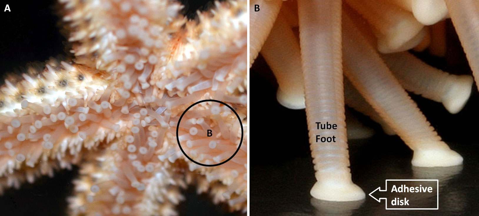
I worked with a PhD student at the Harvard Microrobotics Lab to develop actuators for an underwater, autonomous robot. The purpose of the project was to design feet that can cling to any surface underwater, including ship hulls, as well as gently manipulate samples. Inspired by a sea-star’s tube feet, the basic design is a silicone tube with a deformable membrane that extends with positive pressure and retracts with negative pressure (vacuum). I iterated through various designs of tube feet and studied how they performed under various pressures, recording the minimum pressure to fully extend. The goal was to find a design requiring minimal actuation pressure while maximizing the number of feet that can fit in a small area. In addition to characterizing tube feet designs, we also considered how the tube feet will move the robot. I developed small robots to demonstrate the resulting actuation as seen in this video. I co-authored a paper publishing the results of this research in IEEE Robotics Automation and Letters.
Background
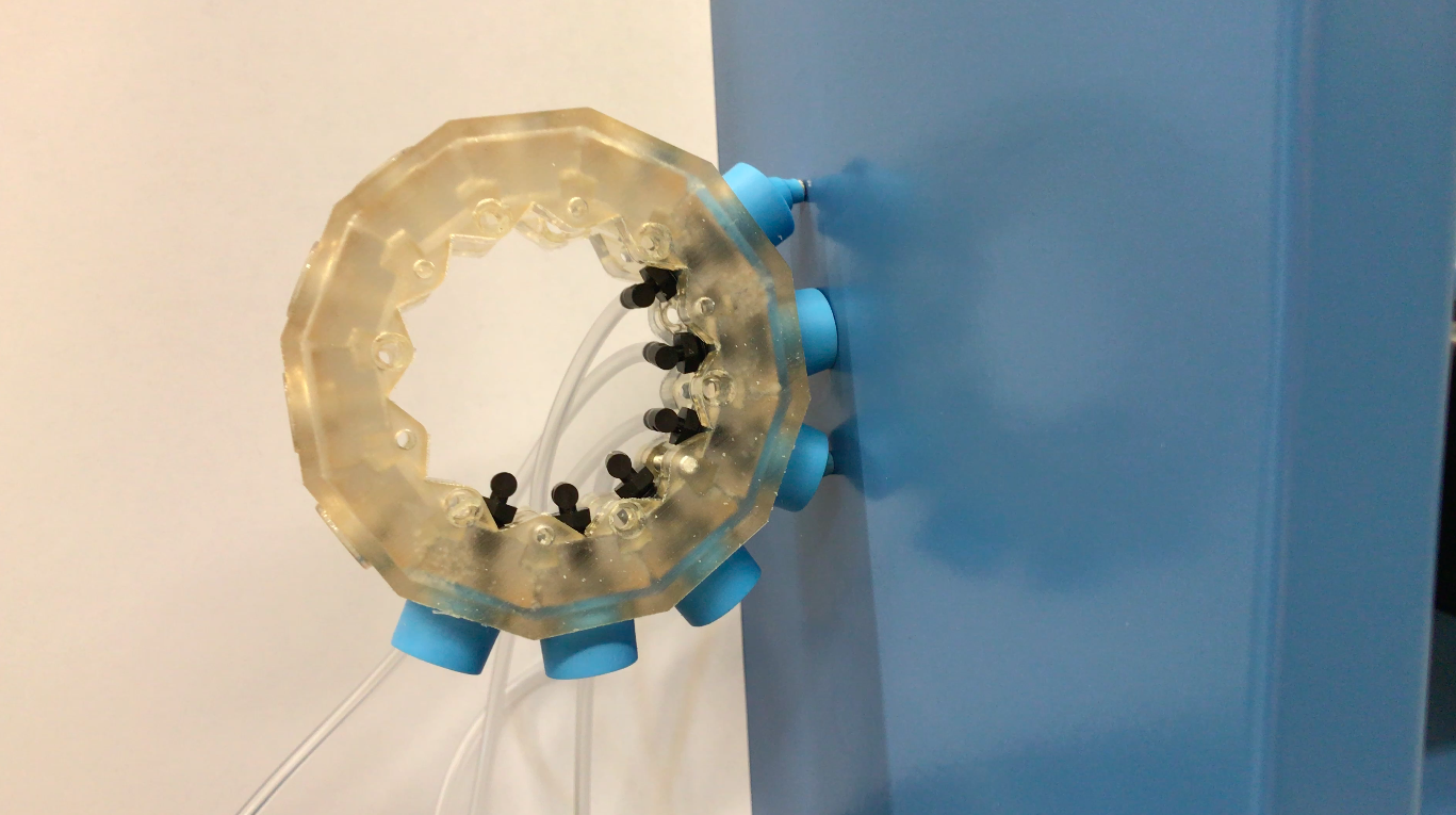
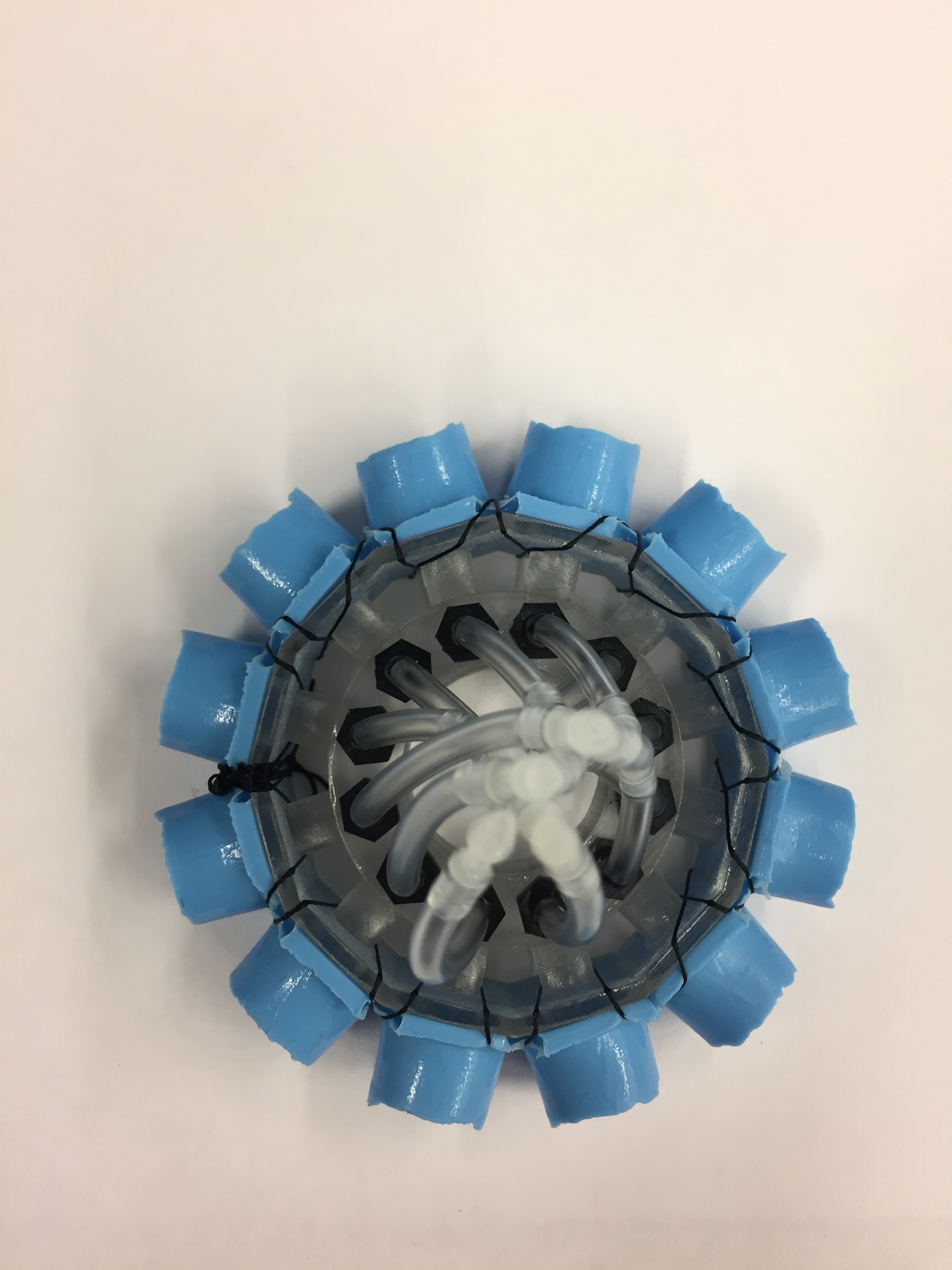
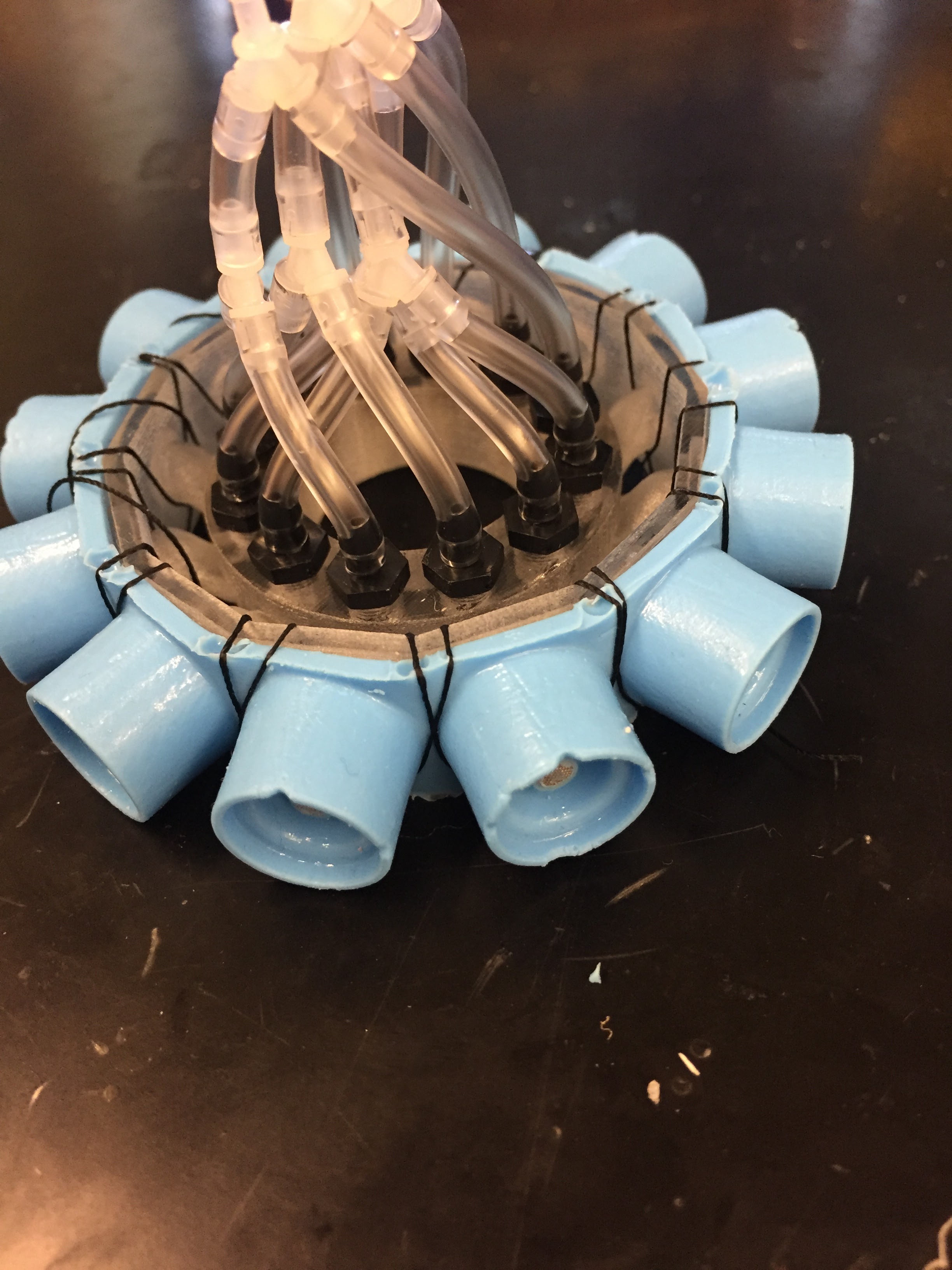
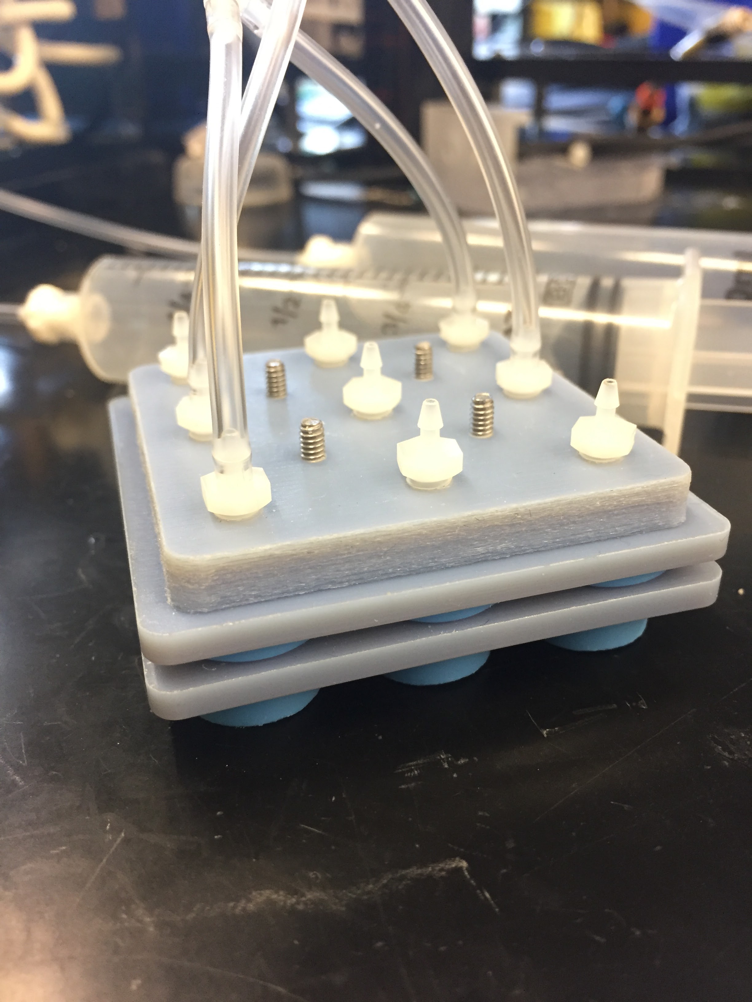
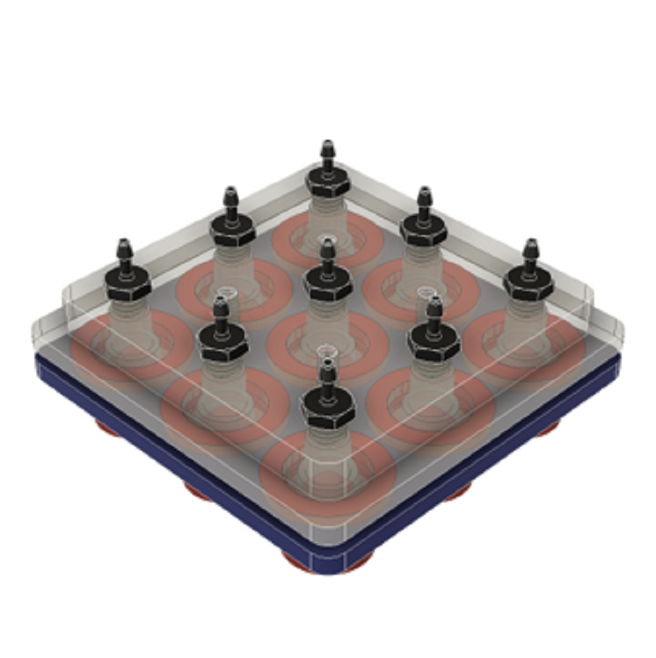
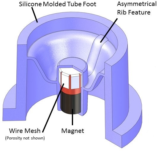
This project was started by a PhD student at the Harvard Microrobotics Lab who designed the tube foot actuator. The tube feet were molded using silicone and contained magnets in the center that would protrude when the tube feet were inflated (cross-section image shown on the right). This allowed the actuators to cling to magnetic surfaces, such as a ship hull. I worked on this project for one summer with the goal of characterizing the tube feet design. The varied parameters included deformable membrane thickness, material, and thickening/rigidity features. In addition, I also designed some prototype robots that demonstrated their climbing and planar movement ability.
Method and Results
My first task was to characterize the actuation pressure for the tube feet. I used the set-up shown in the upper video to the right. Air pumps are controlled using LabVIEW and a laser distance sensor is focused on the center of the tube foot. The distance when the tube foot is fully extended is a known value and is used to mark the actuation pressure. Likewise, the distance when the tube foot is in its neutral position marks the retraction pressure. I cycled each tube foot design through this set-up to record actuation and retraction pressures to see how they changed with design modifications.
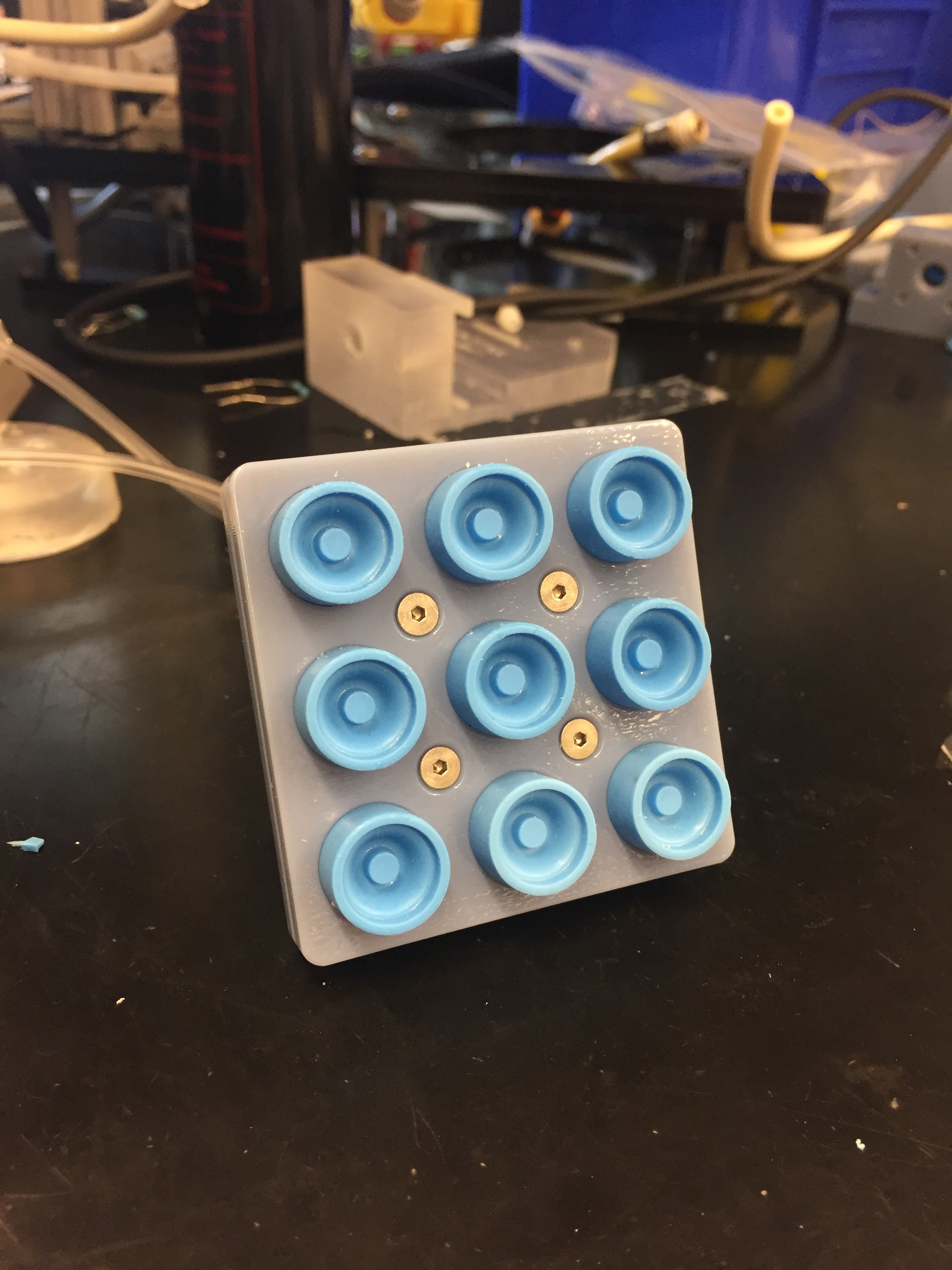
The design feature I spent the most time exploring was a thickened spine that caused directional actuation, i.e. the dome would “kick” out in the direction of the spine. I designed and 3D printed two robots to install the actuators on to explore the limits of this motion. I prototyped the CircleBot and the PlanarBot. The CircleBot has a strip of connected tube feet around the circumference of the robot body (image shown in gallery below). I tested CircleBot’s ability to move up walls and found that the magnets we were using were not strong enough to climb inclines greater than 15 degrees. However, PlanarBot demonstrated better wall adhesion as can be seen in the video below where PlanarBot is climbing down a magnetic wall. PlanarBot has a 3×3 array of the tube feet arranged so that the thickened spines were all oriented in the same direction to produce backward and forward locomotion as can be seen in the video to the right. There is a weight attached to the robot to control the oscillations. The robot doesn’t move in a perfectly straight direction due to the tension in the air lines.