Turbine Collision Detection and Mitigation
2023 / Research Project
Role:
Designer, Fabricator
Timeline:
Fall 2022-Spring 2023
Tools Used:
SolidWorks, MATLAB, Soldering, 3D Printer, Sensor Mounting, FEA
Design Overview
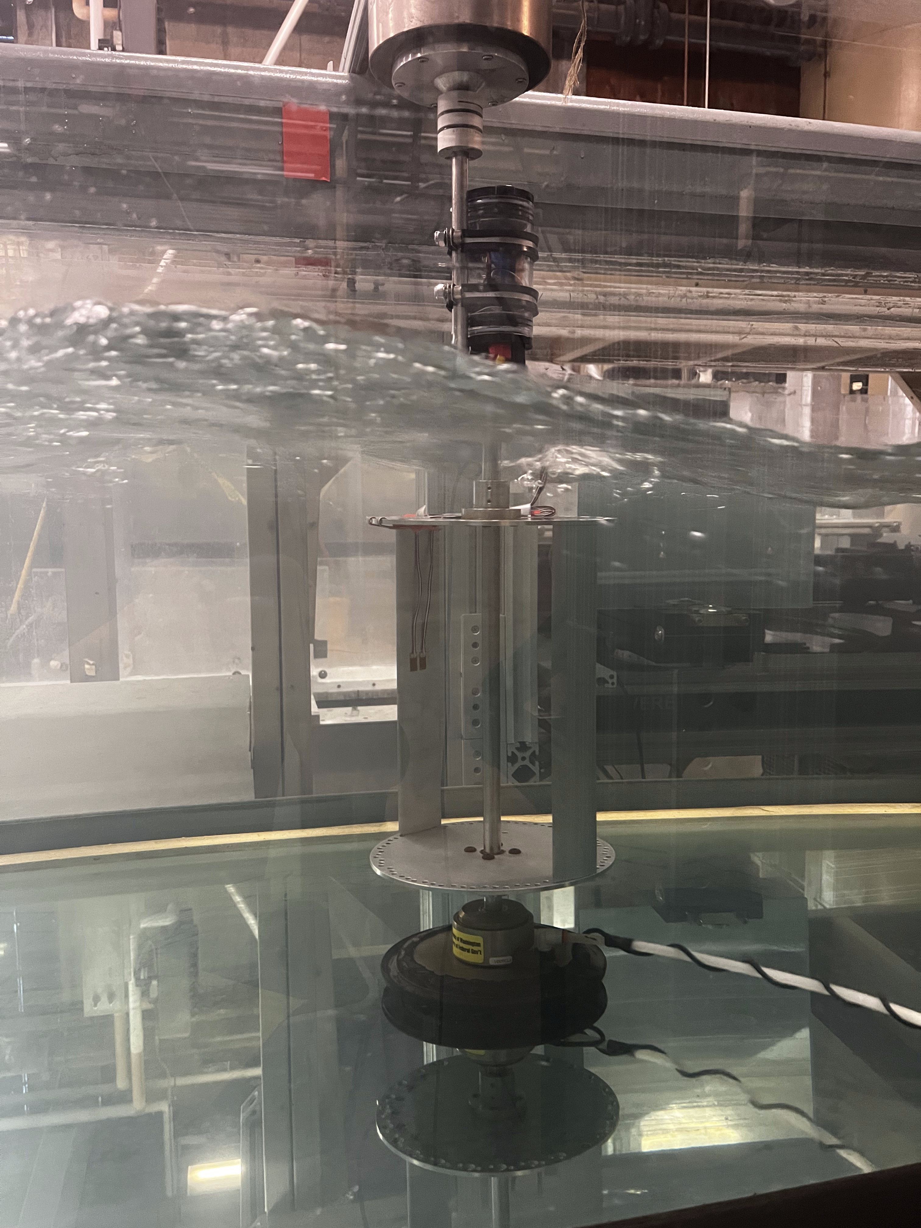
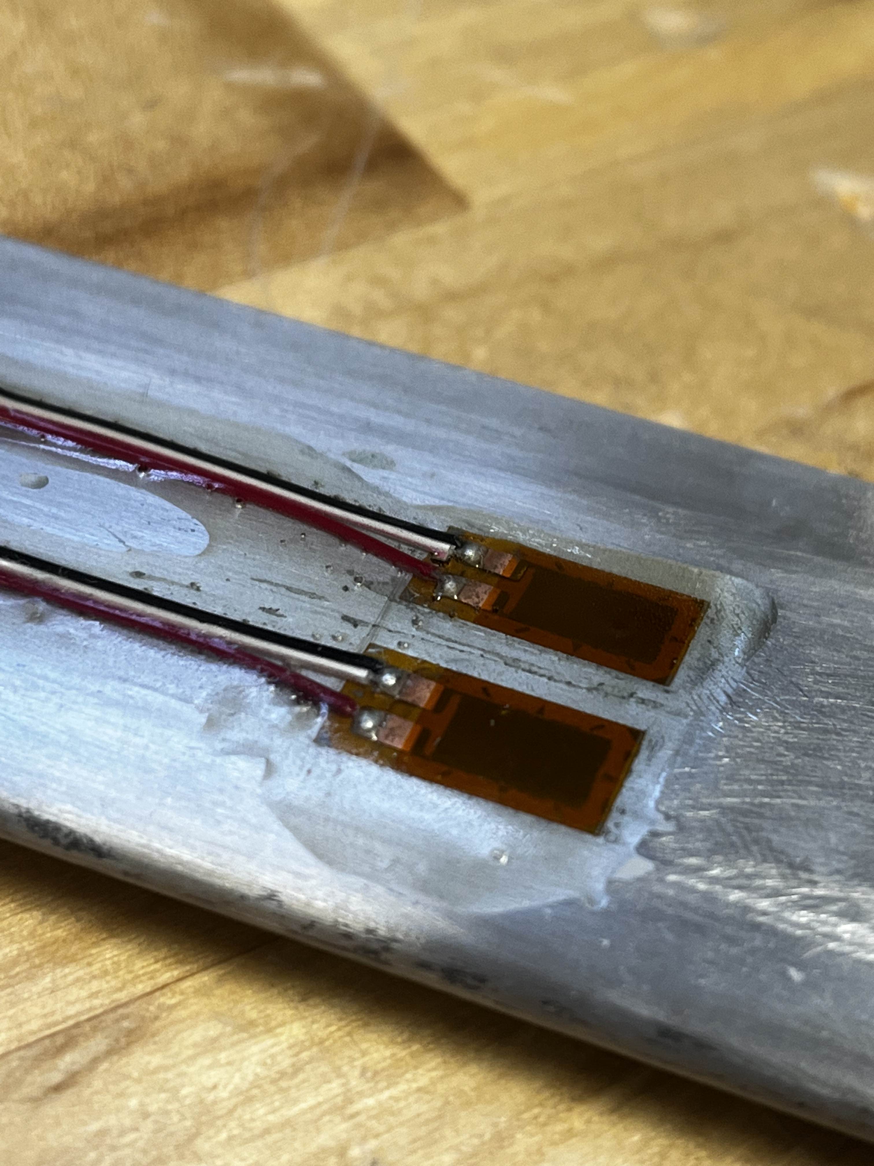
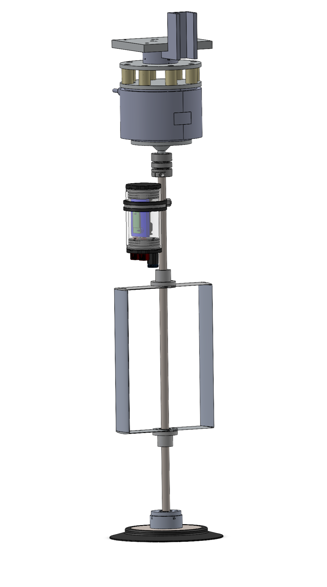
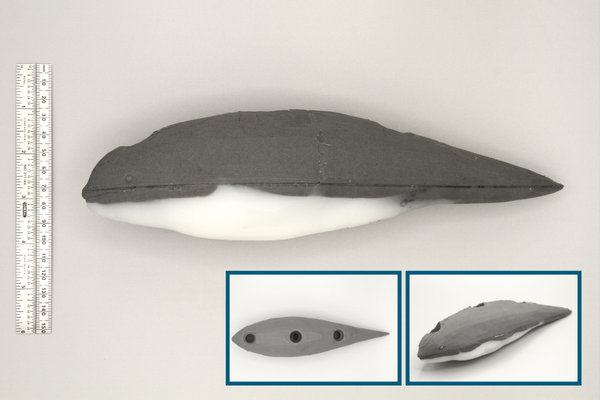
I worked as a graduate research assistant on a project in collaboration with the Pacific Northwest National Laboratory and the University of Washington. The goal of this research was to determine the viability of using strain gauges to detect tidal turbine blade collision with a marine animal. To achieve this, I designed laboratory scale collision experiments in a flume. I mounted strain gauges to a cross-flow turbine blade and used silicone marine mammal models to simulate collisions. The turbine is shown in the image above with the data acquisition unit in a waterproof enclosure secured to the turbine shaft.
Background
This project contributes to ongoing research in underwater turbine collision risk, an area with significant impact on the future of widespread tidal turbine development. Currently, collecting collision data in the field is limited and challenging to gather. This data is typically gathered using optical and acoustic cameras, which record videos and sounds of potential collisions with an installed turbine. These methods cannot quantify the force of an impact, making it difficult to determine the potential harm to the animal. There has been previous research that demonstrates the avoidance behavior of several marine species both in the field and in the laboratory. However there is still a non-zero chance for collision, and for sensitive species these potential collisions have unknown consequences on individuals or populations. There are other examples of mounting strain gauges on turbine blades for monitoring structural integrity, so it seemed fitting to explore their use for detecting collisions in a laboratory setting. More information about the background of the project can be found here.
Method
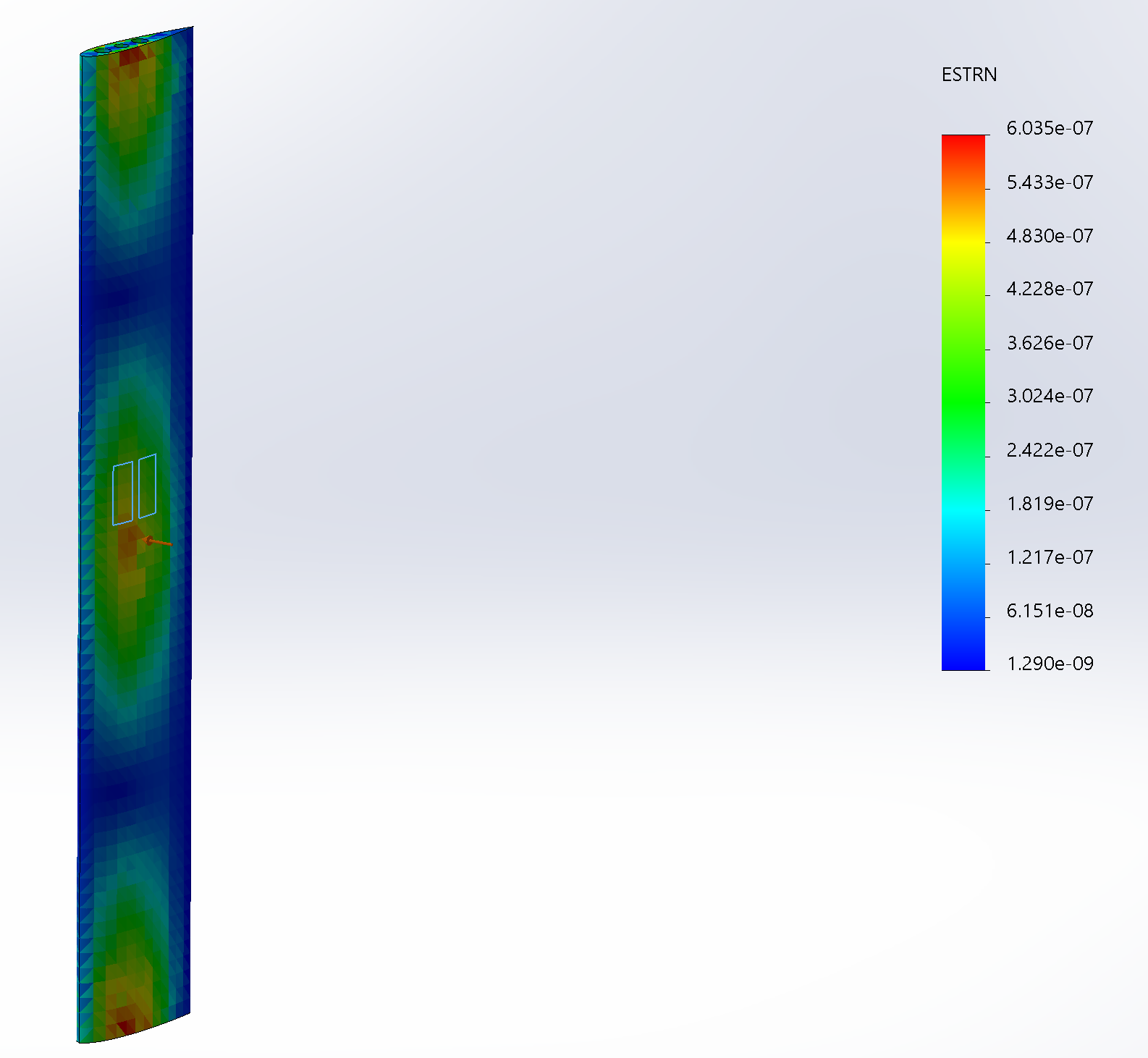
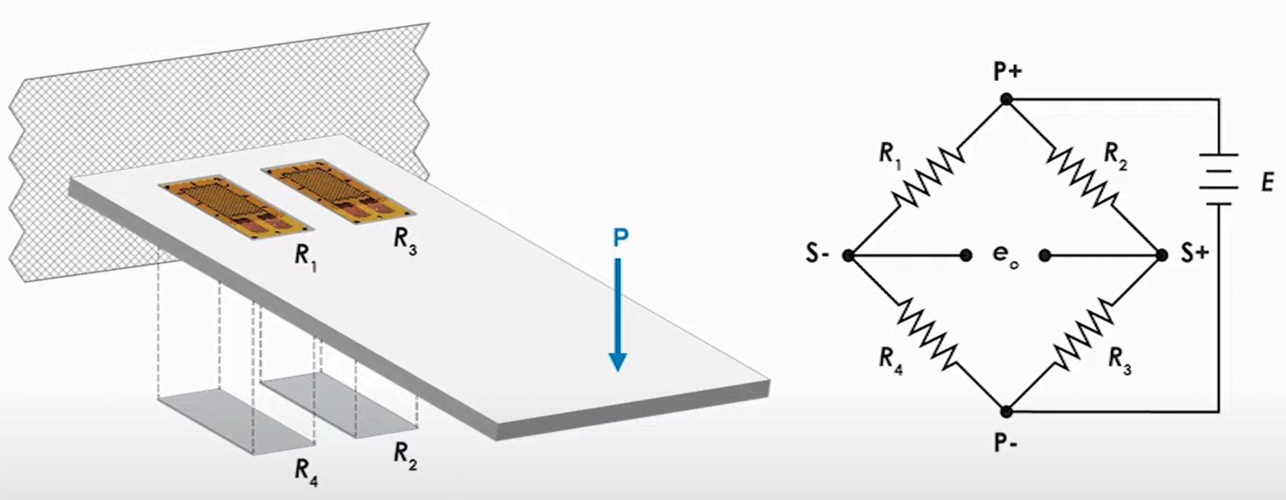
In order to estimate where the strain gauges should be mounted on the blade, I ran a static finite element analysis study in SolidWorks to predict the resulting strain distribution from the simulated collision. An image of the result is shown to the right. After installing the strain gauges and waterproofing them with epoxy, I joined the wires to form a full bridge circuit for bending strain (diagram shown on the right). Before simulating the collisions, I first ran a performance characterization on the turbine to determine the optimal tip-speed ratio, which represents how fast the turbine should be spinning for best power output. This involved sweeping the turbine through a series of tip-speed ratios and calculating the corresponding power output based on torque generated. The optimal tip-speed ratio was used to recreate a realistic situation in which a collision might happen during turbine operation. I control the flume pumps and turbine speed using a MATLAB script.
I will run simulated collision experiments in the flume and use the collected strain data to calculate the force of impact on the blade. I will experiment with different turbine control schemes to determine the effect turbine control has on the severity of collision, thereby exploring methods for mitigating collision risk. Analysis of the experimental data will provide information on the limits of strain gauge based collision detection and the feasibility of real-time, automated collision detection in the field.
Below is a gallery with photos of the experimental set-up and stills of the simulated collisions.